Human Orbital Spaceflights
![]()
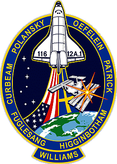
International Flight No. 248STS-116Discovery (33)117th Space Shuttle missionUSA |
 |
 |
 |
||
![]()
Launch, orbit and landing data
walkout photo |
 |
|||||||||||||||||||||||||||||||||
alternative crew photo |
alternative crew photo |
|||||||||||||||||||||||||||||||||
alternative crew photo |
alternative crew photo |
|||||||||||||||||||||||||||||||||
alternative crew photo |
alternative crew photo |
|||||||||||||||||||||||||||||||||
Crew
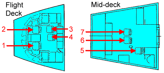
| No. | Surname | Given names | Position | Flight No. | Duration | Orbits | |
| 1 | Polansky | Mark Lewis "Roman" | CDR, RMS | 2 | 12d 20h 44m 23s | 203 | |
| 2 | Oefelein | William Anthony "Bill" | PLT, IV-1 | 1 | 12d 20h 44m 23s | 203 | |
| 3 | Patrick | Nicholas James MacDonald | MS-1, RMS | 1 | 12d 20h 44m 23s | 203 | |
| 4 | Curbeam | Robert Lee, Jr. "Beamer" | MS-2, EV-1, FE | 3 | 12d 20h 44m 23s | 203 | |
| 5 | Fuglesang | Arne Christer | MS-3, EV-2 | 1 | 12d 20h 44m 23s | 203 | |
| 6 | Higginbotham | Joan Elizabeth Miller | MS-4, RMS | 1 | 12d 20h 44m 23s | 203 | |
| 7 | Williams | Sunita Lyn "Suni" | MS-5, EV-3 | 1 | 194d 18h 02m 01s | 3062 |
Crew seating arrangement
|
 |
|
||||||||||||||||||||||||||||||||
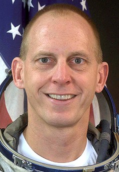
Backup Crew
|
 |
||||||||||
Hardware
| Orbiter : | OV-103 (33.) |
| SSME (1 / 2 / 3): | 2050-2 (5.) / 2054-2 (6.) / 2058-2 (1.) |
| SRB: | BI-128 / RSRM 95 |
| ET: | ET-123 (SLWT-25) |
| OMS Pod: | Left Pod 01 (36.) / Right Pod 03 (34.) |
| FWD RCS Pod: | FRC 3 (33.) |
| RMS: | 303 (18.) |
| EMU (launch): | EMU No. 3003 (PLSS No. 1003) / EMU No. 3018 (PLSS No. 1018) |
| EMU (landing): | EMU No. 3003 (PLSS No. 1003) / EMU No. 3015 (PLSS No. 1015) |
Flight
|
Launch from Cape Canaveral (KSC) and
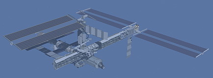
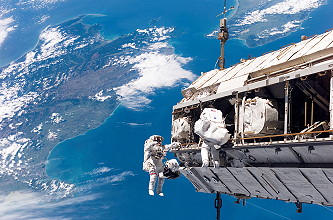
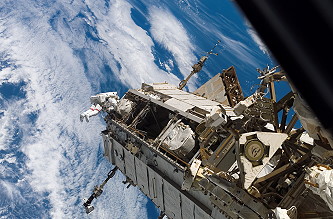
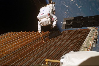
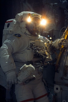
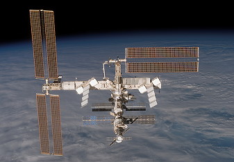
landing at Cape Canaveral (KSC), Runway 15. Liftoff was originally scheduled for December 07, 2006, but that attempt was canceled due to a low cloud ceiling. The main goals of the mission STS-116 (ISS-20-12A.1 SH-LSM ITS-P5) were delivery and attachment of the International Space Station's P5 truss segment, a major rewiring of the station's power system. The shuttle also carried a Spacehab Logistics Module to resupply the ISS, and an Integrated Cargo Carrier with four sub-satellites, which were deployed after undocking from the ISS: the ANDE technology demonstrator, developed by the Naval Research Laboratory, and three CubeSats (RAFT-1 and MARScom for the United States Naval Academy, and MEPSI 2A/2B for DARPA). It was the first Shuttle mission to deploy satellites since STS-113 in 2002. As one of the main goals of STS-116 was to exchange ISS Expedition 14 crew members, the crew of STS-116 changed mid-flight. ISS Flight Engineer Sunita "Suni" Williams was part of the STS-116 crew for the first portion of the mission. She then replaced ISS Flight Engineer Thomas Reiter on the Expedition 14 crew and Thomas Reiter joined the STS-116 crew for the return to Earth. ESA astronaut Christer Fuglesang performed a scientific program as part of the mission Celsius. The primary assembly hardware Discovery will deliver to the space station is the $11-million Integrated Truss Segment P5, which measures 11 feet long by 15 feet wide by 14 feet high (3.3 x 4.5 x 3.2 meters). It will serve as a spacer and be mated to the P4 truss that was attached in September during the STS-115 mission of Atlantis. Attachment of the 4,000-pound (1,800-kilogram) P5 sets the stage for the relocation to its final assembly position of the P6 truss and the pair of solar arrays that have been located temporarily atop the station's Unity module for six years. P5 is part of the 11-segment integrated truss structure and the sixth truss element to be delivered. The truss structure forms the backbone of the International Space Station with mountings for unpressurized logistics carriers, radiators, solar arrays, other hardware and the various elements. P5 is used primarily to connect power and cooling lines and serve as a spacer between the P4 photovoltaic module (PVM), or solar battery, and P6 PVM, which will be joined during a later assembly mission. P5 is very similar in construction to the long spacer located on P6. Without the P5 short spacer, the P4 and P6 solar arrays would not be able to connect due to the way the photovoltaic arrays (PVA) are deployed on orbit. The girder-like structure is made of mostly aluminum and provides several extravehicular aids, robotic interfaces, ammonia servicing hardware (as part of the station's External Active Thermal Control System that allows ammonia fluid to transfer from P4 to P6) and can also accommodate an external storage platform. The Enhanced Universal Trunnion Attachment System (EUTAS) allows platforms to be attached to P5 for the storage of additional science payloads or spare Orbital Replacement Units. P5 also has white thermal blankets on the structure, which help shade the P4 Solar Array Assembly ORUs. The International Space Station (ISS) electrical power system consists of power generation, energy storage, power management, and distribution (PMAD) equipment. Electricity is generated in a system of solar arrays. Besides the solar arrays on the Russian element, the station currently has two photovoltaic modules, a term that refers to a set of solar arrays, batteries and the associated electronics, on orbit, with two more scheduled for delivery. The Electric Power System (EPS) provides all user loads and housekeeping electrical power and is capable of expansion as the station is assembled and grows. Eight independent power channels for high overall reliability supply the electric power. A photovoltaic (PV) electric power generation subsystem was selected for the space station. A PV system uses solar arrays for power generation and chemical energy storage (Nickel-hydrogen) batteries to store excess solar array energy during periods of sunlight and provide power during periods when the station is in Earth's shadow (eclipse). The station orbits the earth every 90 minutes and for about 35 minutes, the station must run on batteries while the station is in eclipse. Flexible, deployable solar array wings that are covered with solar cells provide power for the ISS. Each PV module contains two wings, and each wing consists of two blanket assemblies. The solar array wings are tightly folded inside a blanket for launch. They are deployed in orbit and supported by an extendable mast. Nominal electrical output of each power channel is about 11 kilowatts (kW), or 20.9 kW per PV module. Four PV modules will supply approximately 83.6 kW. The primary purpose of the Energy Storage Subsystem (ESS) is to provide electrical power during periods when power from the solar arrays is not enough to support channel loads. The ESS stores energy during periods when solar arrays can generate more power than necessary to support loads. The system consists of three nickel-hydrogen (Ni-H2) batteries per power channel and each battery consists of two battery Orbital Replacement Units (ORUs). Each battery also has a charge/discharge unit (BCDU). The Ni/H2 battery design was chosen because of its high energy density light weight and proven heritage in space applications since the late 1970s to early 1980s. The entire EPS may be divided into two power subsystems. The primary power subsystem operates at a voltage range of 137 to 173 volts direct current (Vdc) and consists of power generation, storage and primary power distribution. The secondary power subsystem operates at a voltage range of 123 to 126 Vdc and is used to supply power to user loads. Direct Current-to-Direct Current Converter Units (DDCUs) are used to convert primary power to secondary power. The U.S. power system is also integrated with Russian power sources, so that power from the American power bus can be transferred to the Russian power bus and vice versa. The Russian power system operates at a nominal voltage of 28 Vdc. American to Russian Converter Units (ARCUs) and Russian to American Converter Units (RACUs) are used to convert power from the American secondary power bus to the Russian power bus and vice versa. The most powerful solar arrays ever to orbit Earth capture solar energy to convert it into electric power for the ISS. Eight solar array wings supply power at an unprecedented voltage level of 137 to 173 Vdc that is converted to a nominal 124 Vdc to operate equipment on the ISS. The Space Shuttle and most other spacecraft operate at nominal 28 Vdc, as does the Russian ISS segment. The higher voltage meets the higher overall ISS power requirements while permitting use of lighter-weight power lines. The higher voltage reduces ohmic power losses through the wires. Some eight miles of wire distribute power throughout the station. Each PV module contains two solar array wings. An individual wing is 110-feet (33.5 meters) long by 38-feet (11.6 meters) wide. Each wing consists of two array blankets that are covered with solar cells. The blankets can be extended or retracted by a telescopic mast which is located between the two blankets. Each solar array wing is connected to the ISS's 310-foot (94.5 meters) long truss and extend outward at right angles to it (P4 and P6 are currently on orbit). A series of 400 solar cells, called a string, generates electricity at high primary voltage levels while 82 strings are connected in parallel to generate adequate power to meet the power requirement for each power channel. There are a total of 32,800 cells per power channel or 65,600 solar cells on each PV module. A solar cell assembly is about three inches square. The cells are made of silicon and have a nominal 14.5 percent efficiency for sunlight-to-electricity conversion. Cells are welded on to a flexible printed circuit laminate that connects cells electrically. The sun-facing surface of the cell is protected by a thin cover glass. Each group of eight cells, connected in series, is protected by a bypass diode to minimize performance impact of fractured or open cells on a string. Solar arrays are designed for an operating life of 15 years. Two mutually perpendicular axes of rotation are used to point solar arrays towards the Sun. Each solar array wing is connected to one Beta Gimbal Assembly (BGA), located on each PV module, that is used to rotate that solar array wing. Another rotary joint, called Solar Alpha Rotary Joint (SARJ), is mounted on the truss and rotates the four solar array wings together. When the station is complete, there will be eight BGAs and two SARJs. These rotary joints are computer controlled and ensure full sun-tracking capability as the ISS goes around the earth under a wide range of orbits and ISS orientations. Flight day 2 began for the astronauts at 15:47 UTC. The first order of business for the day was a thorough inspection of the Shuttle. Using sensors and cameras attached to a fifty-foot (15 meters) boom, which was in turn connected to a fifty-foot robotic arm, Nicholas Patrick inspected the leading edge of the wings and the nose cap. The process, which took five and a half hours, suffered a minor glitch that required Nicholas Patrick to order the arm to manually grab the boom. During this time, the crew also inspected the upper surface of the orbiter. Astronauts also completed a check of the spacesuits to be used during the mission, along with preparation for docking with the International Space Station. Discovery's final approach to the International Space Station during the STS-116 rendezvous and docking process included the now-standard back flip pirouette maneuver to allow station crewmembers to take digital images of the shuttle's heat shield. With shuttle Commander Mark Polansky at the controls, the shuttle performed the circular pitch-around from a distance of about 600 feet (182.9 meters) below the station. The 9-minute flip offers Expedition 14 Commander Michael Lopez-Alegria and Flight Engineer Mikhail Tyurin time to document through digital still photography the required imagery of Discovery's thermal protection system. The photos then were transmitted to imagery experts in the Mission Evaluation Room at Mission Control, Houston, via the station's Ku-band communications system. The photography was performed out of windows 6 and 8 in the Zvezda Service Module with Kodak DCS 760 digital cameras and 400 mm and 800 mm lenses. The Rendezvous Pitch Maneuver (RPM) or R-bar Pitch Maneuver (RPM) was one of several inspection procedures designed to verify the integrity of the shuttle's protective tiles and reinforced carbon-carbon wing leading edge panels. The sequence of events that brought Discovery to its docking with the station began with the precisely timed launch of the shuttle, placing the orbiter on the correct trajectory and course. The sequence of events that culminate with Discovery's docking to the station actually began with the precisely timed launch that places the orbiter on course for its two-day chase to arrive at the station. The 43-hour rendezvous included periodic thruster firings that ultimately placed Discovery about 9 statute miles (15 km) behind the station, the starting point for final approach. About 2.5 hours before the scheduled docking time on flight day 3, Discovery reached a point about 50,000 feet (15,240 meters) behind the station. Discovery's jets were fired in what is called the Terminal Initiation (TI) burn to begin the final phase of the rendezvous. Discovery closed the final miles to the station during the next orbit. As Discovery moved closer to the station, the shuttle's rendezvous radar system and trajectory control sensor (TCS) began tracking the complex, and providing range and closing rate information to the crew. During the final approach, Discovery executed four small mid-course corrections with its steering jets to position the shuttle about 1,000 feet (304.8 meters) directly below the station. From this point, Mark Polansky took over the manual flying of the shuttle up an imaginary line drawn between the station and the Earth known as the R-Bar - or radial vector. He slowed Discovery's approach at about 600 feet (182.9 meters) and waited for proper lighting conditions to optimize inspection imagery gathering as well as crew visibility for the final rendezvous to docking. On verbal confirmation by Pilot William Oefelein to alert the station crew, Mark Polansky commanded Discovery to begin a nose forward, three-quarters of a degree per second rotational back flip. At R-bar Pitch Maneuver (RPM) start, the station crew began a series of precisely-timed photography for inspection. The sequence of mapping optimizes the lighting conditions. Both the 400 mm and 800 mm digital camera lenses were used to capture imagery of the required surfaces of the orbiter. The 400 mm lens provided up to 3-inch (7.6 centimeters) resolution and the 800 mm lens could provide up to 1-inch (2.5 centimeters) resolution and detect any gap filler protrusions greater than ¼ inch (6.4 mm). The imagery included the upper surfaces of the shuttle as well as Discovery's underside, nose cap, landing gear door seals and the elevon cove areas with 1-inch (2.5 centimeters) analytical resolution. The photography included detection of any gap filler protrusions when the orbiter is at 145 and 230-degree angles during the flip. The maneuver and lighting typically offered enough time for two sets of pictures. When Discovery completed its rotation, it returned to an orientation with its payload bay facing the station. Mark Polansky then moved Discovery to a position about 400 feet (121.9 meters) in front of the station along the V-Bar, or the velocity vector - the direction of travel for both spacecraft. William Oefelein provided navigation information to Mark Polansky as the shuttle inched toward the docking port at the forward end of the station's Destiny Laboratory. William Oefelein joined Mission Specialists Nicholas Patrick and Joan Higginbotham in playing key roles in the rendezvous. They operated laptop computers processing the navigational data, the laser range systems and Discovery's docking mechanism. Using a camera view from center of Discovery's docking mechanism as a key alignment aid, Mark Polansky precisely matched the docking ports of the two spacecraft and flew to a point 30 feet (9.14 meters) from the station before pausing to verify the alignment. For Discovery's docking on December 11, 2006, Mark Polansky closed the final 30 feet (9.14 meters) at a relative speed of about one-tenth of a foot per second (3 centimeters per second) (while both spacecraft were traveling 17,500 mph = 28,163 km/h), and kept the docking mechanisms aligned within a tolerance of three inches (7.6 centimeters). At contact, preliminary latches automatically attached the two spacecraft. Immediately after Discovery docked, the shuttle's steering jets were deactivated to eliminate forces acting at the docking interface. Shock absorber-like springs in the docking mechanism dampened any relative motion between the shuttle and the station. Once motion between the two spacecraft had stopped, Mission Specialists Robert Curbeam and Christer Fuglesang secured the docking mechanism, sending commands for Discovery's docking ring to retract and to close a final set of latches between the two vehicles. The docking set the stage for the opening of the hatches and the start of joint operations, including the transition of Sunita Williams to the Expedition 14. After docking, the first priority was to transfer form-fitting seat liners in the Soyuz spacecraft making Sunita Williams an official member of the Expedition 14 crew along with Commander Michael Lopez-Alegria and Flight Engineer Mikhail Tyurin. Thomas Reiter then became a member of the shuttle crew with which he returned home after a six-month stay on the station. On flight day 3, Nicholas Patrick carefully lifted the P5 spacer with the shuttle RMS and handed it to the waiting station arm. Joan Higginbotham and Sunita Williams controlled the station arm at the station's robotic work station in the Destiny Laboratory. The spacer remained on the station's arm overnight in preparation for installation the next day during the first of three planned spacewalks. The first EVA by Robert Curbeam and Christer Fuglesang occurred on December 12, 2006 (6h 36m) to align and connect the P5 truss segment to P4. They also replaced a faulty video camera attached to the S1 truss. Since they worked ahead of the time-line, the two astronauts were also able to complete some get-ahead tasks. On flight day 4, the station's arm - the Space Station Remote Manipulator System or SSRMS - was used to move the P5 spacer to a pre-installation position on the left, or port, side of P4. Once the P5 is in position, Robert Curbeam and Christer Fuglesang removed the locks that secured the spacer's hardware during its launch on the shuttle. Robert Curbeam removed the P5 launch locks from corners 3 and 1. Christer Fuglesang removed locks from corners 2 and 4. Once the locks were removed, the two provided verbally guide Sunita Williams as she maneuvered the station arm to align P5 to P4. The installation was completed by mating six utility cables. Before the P5 was locked in place, Mission Control had to take several measures to ensure nothing disturbs the operation. The station's thrusters were turned off and the control moment gyroscopes were in a mode that creates as little disturbance as possible until the crew had tightened three of the four Modified Rocketdyne Truss Attachment System (MRTAS) bolts. Mission Control configured the Solar Alpha Rotary Joint and Beta Gimbal Assemblies - used to swivel the solar arrays to allow them to track the sun - into the proper positions for P5 installation. All of the joints were locked to ensure there is no unexpected motion. After the P5 launch locks were removed, the station robotic arm guided P5 into the soft capture position, with Robert Curbeam and Christer Fuglesang assisting by monitoring structural clearances. Once the P5 coarse alignment cone had captured the P4 soft capture pin, the spacewalkers used a pistol grip tool - similar to a portable hand drill - to tighten the attachment bolts. First the bolts on corner 1 (forward/zenith) and 2 (forward/nadir) were tightened, in that order, to an initial torque. Next, bolts on corners 3 (aft/zenith) and 4 (aft/nadir) were driven to final torque. Finally, bolts 1 and 2 were tightened to their final torque. After the bolts were driven, the crew attached grounding straps on each corner and removed the soft capture pins. Next, the crew moved the Photovoltaic Radiator Grapple Fixture (PVRGF) from the P5 to a place on the station's Mobile Base System. The grapple fixture was temporarily stored there until it could be moved to the P6 aft radiator on a later spacewalk. The PVRGF is a handle that was installed on the top, or zenith, side of the P5 spacer and used by the shuttle and station arms to move the truss. It is being removed to provide enough clearance for the solar arrays to rotate and track the sun. To accomplish this, Robert Curbeam and Christer Fuglesang moved to the grapple fixture, where Robert Curbeam used the pistol grip tool to begin removing fasteners. Meanwhile, Christer Fuglesang moved a foot restraint to a new worksite interface. Once the foot restraint was in place, Christer Fuglesang began removing grapple fixture fasteners. Once all the fasteners were removed, Christer Fuglesang and Robert Curbeam performed an almost acrobatic transfer of the tethered grapple fixture from one to the other as they moved to the station's keel. The final task for this spacewalk was the removal and replacement of a camera located at port 3 of the station's starboard 1 (S1) truss. The camera is needed to view clearances during future installations and deployments. Robert Curbeam set up the worksite while Christer Fuglesang retrieved the replacement camera from the airlock. Both worked to remove the failed camera and installed the new one. On December 13, 2006, the crew attempted retraction of the P6 port-side solar array. Problems with the array folding due to 'kinks' and 'billows' led the controllers to redeploy the array (from about 40% retracted). There then followed a series of more than 40 commands to furl and unfurl the arrays in an effort to get them properly aligned and folded. The retraction efforts were abandoned for the day. The second EVA was performed by Robert Curbeam and Christer Fuglesang on December 14, 2006 (5h 00m) to reconfigure power on channels 2 and 3 of the station's electrical system. First, Robert Curbeam and Christer Fuglesang reconfigured power on the Channel 2/3 side of the station's Electrical Power System to route it through the Main Bus Switching Units. The power reconfiguration required that all power was shut down from Channel 2/3. To accomplish this, a lengthy set of power down procedures were executed from the ground while the crew prepared for the spacewalk. During the spacewalk, primary power from channels 2A and 2B were connected to the main bus switching unit 2. The work was done at the Starboard 0 (S0) truss segment near the forward S0-Lab struts. Robert Curbeam translated to the S0 to disconnect the lab's secondary power, installed a cable to route power from the S0 truss to the P1 truss, and reconfigured the S0-2B dc converter unit, the bypass jumper on the main bus switching, and the P1-3A dc converter. The S0 truss segment sits in the middle position on the truss structure on top of the U.S. Destiny Laboratory, flanked by the S1 and P1 truss elements. That truss, along with the S1 and P1 trusses, contain the major electrical components of the permanent electrical system, including the main bus switching units and the DC-to-DC converter units. The power produced by the station's solar arrays is routed to batteries for storage and then to the main bus switching units. The main buses route power to DC-to-DC converter units (DDCUs) which then adjust the primary, 160-volt dc electricity it receives from the main buses to about 125 volts of power. The dc converters feed the station through the Remote Power Controller Modules (RPCMs). A simplified comparison is that the main buses are similar to a power substation, the dc converters are like transformers, and the controller modules are like the electrical switches inside a home. While Robert Curbeam was configuring power to the Unit 2 main bus, Christer Fuglesang were removing Circuit Interrupt Devices (CIDS) 3, 4, and 5. Once the main bus is operating, the circuit interrupt devices won't be needed. The circuit interrupts served as early "circuit breakers" for the crew. They were returned to Earth. All three circuit interrupters are located at the lab's aft end cone panel, in an area known as "the rat's nest". Because the main bus switching unit generates heat once it is activated, a pump module must also be activated to enable ammonia to flow through large cold plate loops that cool the bus. Prior to both the second and the third spacewalks, the station's External Thermal Control System (ETCS) ammonia loops were filled so they are ready when the buses are activated. Once the EVA crewmembers had finished the Channel 2/3 power reconfiguration, they began other tasks while Mission Control powered up the station. Robert Curbeam and Christer Fuglesang relocated two crew and equipment translation aid (CETA) carts from their current locations on the S1 truss to the S0 truss to clear the way for Atlantis' astronauts to install the S3 and S4 truss segments on the STS-117 mission. The crew also installed a thermal cover on the force moment sensors on the latching end effector on the station's robotic arm and reconfigured power to the Z1 truss electrical patch panel 6, which provides power to the Z1 truss as well as the Russian segment. The electrical panel task must be conducted separately from the main power down because the S-band communication antennas powered by Channel 2/3 are sensitive to cold and should not be shut down for a protracted period of time. While Robert Curbeam was busy with this reconfiguration, Christer Fuglesang retrieved the starboard and port quick disconnect bags - stowage bags filled with maintenance hardware and tools - from the airlock and installed the bags on top, or the zenith side, of the airlock. The third EVA by Robert Curbeam and Sunita Williams was conducted on December 16, 2006 (7h 31m) to reconfigure power on channels 1 and 4 of the station's electrical system. The third spacewalk on flight day 8 was basically a repeat of the flight day 6 power reconfiguration activities. During EVA 3, the Channel 1/4 side of the station's Electrical Power System was reconfigured to route primary power through the Main Bus Switching Units. As on flight day 6, this spacewalk required that all power be shut down - this time from Channel 1/4. Again, a lengthy set of power down procedures were executed from the ground while the crew prepared for the walk. The work again was at the Starboard 0 (S0) truss segment. Robert Curbeam reconfigured the S0 forward starboard avionics and the S1-4B and S0-1A dc converters, disconnected the secondary power Lab 4A dc converters, routed the S0/N1 power cable, and reconfigured the bus bypass jumper. While he was disconnecting and connecting cables, Sunita Williams removed the 1 and 2 circuit interrupt devices and reconfigured the other half of the Z1 truss electrical patch panel 5. The circuit interrupters were returned on the shuttle. Also, during the Z1 patch panel task, the crew ventured out to the Russian segment interface at Node 1 and reconfigured the Russian power feeds from the U.S. segment. This reconfiguration allowed the Russians to draw additional power from the U.S. segment by moving some of their power feeds to larger switches, capable of transferring more current, should that be needed. As Robert Curbeam and Sunita Williams reconfigured external power connectors, the crew inside reconfigured an electrical patch panel in the Destiny lab. This new configuration will provide twice as much power for payload use. Once power was reconfigured for Channel 1/4, Robert Curbeam and Sunita Williams moved to the shuttle's payload bay to attach three Service Module Debris Panel bundles (SMDPs) on to an adapter. The three bundles and adapter were launched on the Integrated Cargo Carrier (ICC), a pallet located at the rear of the payload bay. Once the bundles were attached to the adapter, the assembly is referred to as "the Christmas tree". Sunita Williams worked from the shuttle arm to move the "Christmas tree" to stow it on the grapple fixture located on the aft side of the Pressurized Mating Adapter 3. The bundles are composed of individual panels that were installed on the Service Module to provide additional micrometeroid debris protection. While Sunita Williams completed clean-up of the task, Robert Curbeam moved to reconfigure power to the Z1 truss electrical patch panel 1. During the third spacewalk, Robert Curbeam and Sunita Williams also transferred the Adjustable Grapple Bar (AGB) - a portable handle that can be installed on objects to make it easier for the crew to move them around during spacewalks - to the Flex Hose Rotary Coupler (FHRC) on the airlock's External Stowage Platform-2, where it was stowed for future use. As an "add-on task" to the EVA, astronauts Robert Curbeam and Sunita Williams also continued work on the retraction of a sticking solar array, enabling the retraction of another six sections of the P6 array. At the end of the EVA there were another 11 "bays", or 35% left to retract. The fourth and unplanned EVA by Robert Curbeam and Christer Fuglesang was performed on December 18, 2006 (6h 38m) to try to fully close the last eleven bays of the balky P6-port Solar Array Wing. The rapidly planned EVA was successfully completed. With additional inspections of Discovery's heat shield after undocking, the orbiter departed the station with the shuttle robotic arm and Orbiter Boom Sensor System (OBSS) in their stowed configuration. The OBSS was unstowed to accommodate the inspections. Once Discovery was ready to undock, Christer Fuglesang sent a command to release the docking mechanism. At initial separation of the spacecraft, springs in the docking mechanism pushed the shuttle away from the station. Discovery's steering jets were shut off to avoid any inadvertent firings during the initial separation. Once Discovery was about two feet (61 centimeters) from the station, with the docking devices clear of one another, William Oefelein activated the steering jets to very slowly move away. From the aft flight deck, William Oefelein manually controlled Discovery within a tight corridor as it separated from the station - essentially the reverse of the task performed by Mark Polansky during rendezvous. Discovery continued away to a distance of about 450 feet (137.2 meters), where William Oefelein guided the shuttle in a circular flyaround of the station. Once Discovery completed 1.5 revolutions of the complex, William Oefelein fired Discovery's jets to depart the station's vicinity for the final time. Discovery separated to a distance of about 40 nautical miles (74 km) and remained there to protect for a return to the complex in the unlikely event the late inspection reveals any damage to the shuttle's thermal heat shield. Flight day 12 began for the astronauts at 12:48 UTC. They spent the day verifying the integrity of Discovery's heat shield and preparing for deorbit and landing on December 22, 2006 (Flight day 14). Because of the extended spaceflight, the shuttle was required to make a landing attempt on flight day 14 unless all three landing sites were "no-go". Two satellites were also launched: MEPSI (Microelectromechanical System-Based PICOSAT Inspector) resembles a pair of tethered coffee-cups, and is being tested as a reconnaissance option for disabled satellites; RAFT (Radar Fence Transponder) is a pair of 5" (12.7 centimeters) cubes built by the U.S. Naval Academy which will test space radar systems and also act as data relays for mobile ground communications. On flight day 13 Discovery's crew launched the ANDE (Atmospheric Neutral Density Experiment) microsats for the Naval Research Laboratory, which were designed to measure the density and composition of the low Earth orbit atmosphere in order to help better predict the movements of objects in orbit, but one of the satellites failed to emerge from its launch canister. ANDE is currently transmitting data, and emerged from the canister approximately 30 minutes after its launch according to satellite tracking data. High cross-winds precluded a landing at Edwards Air Force Base while clouds and showers were an issue at Kennedy Space Center Shuttle Landing Facility on the first orbit. That combination raised the possibility of the first landing at White Sands Space Harbor since STS-3 in 1982. Had landing taken place at White Sands, it could have taken as long as 60 days to return the orbiter to Kennedy Space Center. The first landing opportunity at Kennedy Space Center was abandoned due to unfavorable weather conditions. However, at 21:00 UTC coordinates were sent to the shuttle to re-attempt a landing at Kennedy along runway 15, as the first contingency landing attempt at Edwards had been scrubbed due to high cross winds. |
EVA data
| Name | Start | End | Duration | Mission | Airlock | Suit | |
| EVA | Curbeam, Robert | 12.12.2006, 20:31 UTC | 13.12.2006, 03:07 UTC | 6h 36m | STS-116 | ISS - Quest | EMU No. 3003 |
| EVA | Fuglesang, Christer | 12.12.2006, 20:31 UTC | 13.12.2006, 03:07 UTC | 6h 36m | STS-116 | ISS - Quest | EMU No. 3018 |
| EVA | Fuglesang, Christer | 14.12.2006, 19:41 UTC | 15.12.2006, 00:41 UTC | 5h 00m | STS-116 | ISS - Quest | EMU No. 3018 |
| EVA | Curbeam, Robert | 14.12.2006, 19:41 UTC | 15.12.2006, 00:41 UTC | 5h 00m | STS-116 | ISS - Quest | EMU No. 3003 |
| EVA | Curbeam, Robert | 16.12.2006, 19:25 UTC | 17.12.2006, 02:56 UTC | 7h 31m | STS-116 | ISS - Quest | EMU No. 3003 |
| EVA | Williams, Sunita | 16.12.2006, 19:25 UTC | 17.12.2006, 02:56 UTC | 7h 31m | STS-116 | ISS - Quest | EMU No. 3018 |
| EVA | Curbeam, Robert | 18.12.2006, 19:00 UTC | 18.12.2006, 01:38 UTC | 6h 38m | STS-116 | ISS - Quest | EMU No. 3003 |
| EVA | Fuglesang, Christer | 18.12.2006, 19:00 UTC | 18.12.2006, 01:38 UTC | 6h 38m | STS-116 | ISS - Quest | EMU No. 3015 |
Note
Photos / Graphics
 |
 |
 |
 |
 |
 |
 |
 |
 |
 |
 |
 |
 |
 |
 |
 |
 |
 |
 |
 |
more EVA photos |
|
| © |  |
Last update on March 27, 2020.  |
 |